Comms Cabinet Controller/Monitor

This project was a real “Parts-bin Special”; made up from a load of stuff I’ve had hanging around at the bottom of boxes for years. What it does is pretty useful to me, though.

Last year I networked my entire house with a gigabit LAN. CAT6A cable runs from RJ45 sockets all over the house up to the loft where they are terminated at a patch-panel in a 6U 19 inch rack-mount cabinet. This cabinet houses a 24-port switch, router, cable-modem, and a server (an Intel i5 with 8GB of RAM in a 2U case, in case you’re interested). For a few days last year the sun did actually shine on my house, and subsequently the temperature in the loft rose alarmingly quickly. The power led on the cable-modem changed from blue to pink – a quick visit to Google confirmed that it was getting too hot. My quick fix consisted of running a couple of old CPU fans over the modem and router, and removing the door and side-panels of the cabinet. It worked, but was hardly a long-term solution.

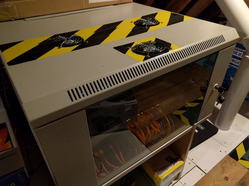
There was nothing for it but to break-out the power-tools, and cut holes in the cabinet to permanently fit some fans.
Cabinet Fans
Cabinet Fans

All well-and-good, but how to control the fans? I was glad to finally find a use for the following stuff that I’d probably bought for various long-forgotten projects!:

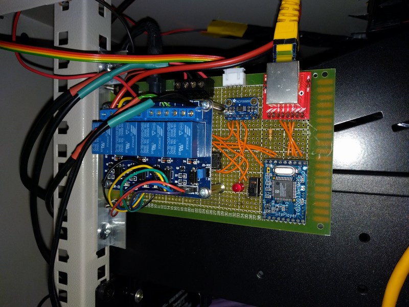
Cabinet Controller/Monitor Circuit
Cabinet Controller/Monitor Circuit (it ain’t pretty, I know!)

When built, programmed, and mounted in the cabinet it give me the following functionality:

Fan Control

When the cabinet temperature (measured by the MCP9808) reaches 30°C the fans switch on. They will only switch off when the cabinet temperature falls below 26°C. If the server is running then the fans are switched on regardless of the cabinet temperature.

Cable Modem Control

Very occasionally the cable-modem needs rebooting. Being mounted in the loft used to mean that someone (that would be me, then) would have to climb up the ladder to pull the power from the back of the modem, wait 30 seconds, then reconnect it. Somewhat inconvenient. The modem power is now routed through one of the relays via its normally-closed connection which can be switched remotely.

Server & NAS Control

The server and NAS have their power switches connected in parallel with 2 of the relays, allowing a simulated button-push to turn them on and off.

Loft Temperature & Humidity Monitoring

The HTU21D-F is mounted outside the cabinet to provide monitoring functions (no reason for this, really – it was just easy to add!)

All the above is accessed via a mobile optimised web-page:
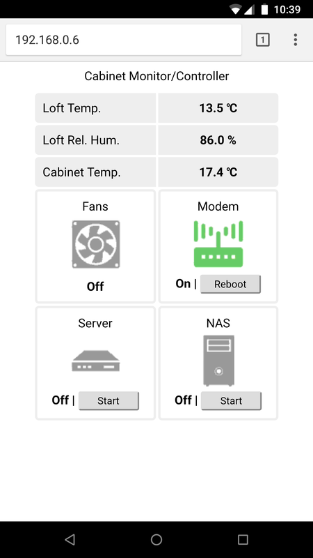
Cabinet Controller/Monitor Web Interface

The take-away from this post is this:

You probably can build something cool from the long-forgotten components you already have – get to it!

ATmega328 Programming Cables

After using pre-built Arduinos the next step is to ‘roll your own’. It may not have the niceties of built in USB/debug-console, but it’s fully functional (and much cheaper!).

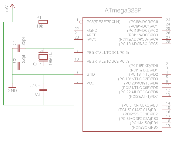
There are plenty of tutorials on DIY Arduino compatible circuits, so there’s no point duplicating that information here. As a reminder, however, here is what you need to make a minimal Arduino:

  • AVR ATmega328 Microcontroller
  • 16MHz Crystal
  • 22pF Capacitor (x2)
  • 10k Resistor
  • 10uF Capacitor
Minimal Arduino circuit

So far, so good – but with no built-in USB interface you’ll have to use either an FTDI interface (for ATmegas with a bootloader already installed), or an ICSP interface (for blank ATmegas).

FTDI Method:

To use this method you’ll need an ATmega328P that has had the Arduino bootloader pre-installed. This is a small piece of code that allows sketches to be uploaded via the microcontroller’s serial link. You’ll also need a USB to FTDI interface. I wholeheartedly recommend Adafruit’s FTDI Friend product.

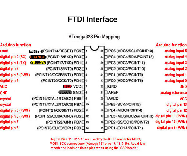
The FTDI interface is connected to the ATmega328P thus:

ATmega328 FTDI Connections


Building in a programming header into your project that plugs directly into the FTDI interface can be a bit of a pain – routing the connections around the circuit takes time and space, and adds to the complexity. I prefer to simply put header pins next to the relevant ATmega pins, then use an adapter with flying leads. Another advantage is that the 0.1uF capacitor can be built into the adapter, as its only required when programming the device.


FTDI Cable
FTDI Cable


Another good idea is to make a handy reference to remind you what goes where. Print this out (laminate it if you can) and keep it with the adapter:

ATmega328 FTDI Header Pins
ICSP Method:

For this method you’ll need an ICSP interface. You’ve got a lot of options when choosing one. I use the official ArduinoISP – although it is apparently no longer made.

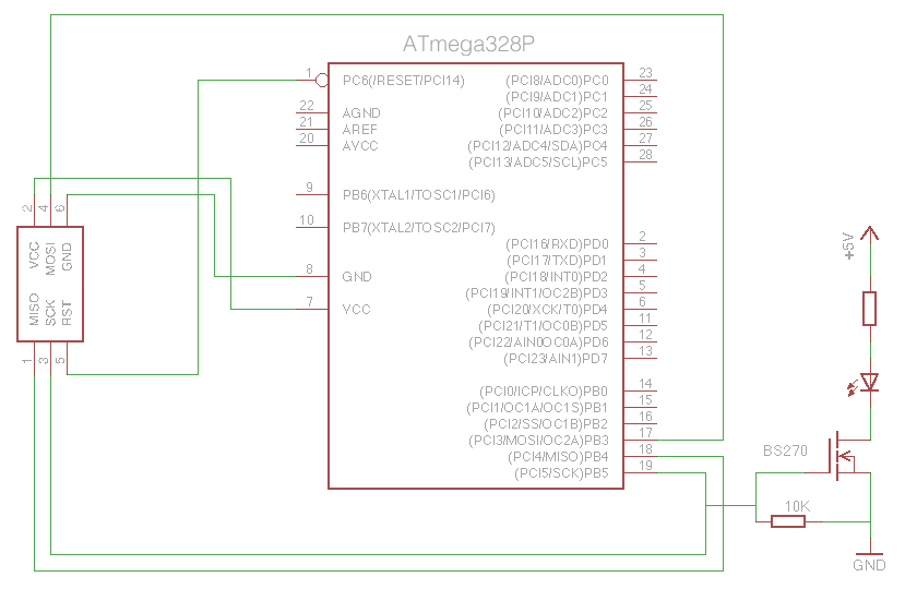
One of the things I don’t like about the ArduinoISP is the lack of status LEDs showing activity. Adafruit’s FTDI Friend features blinking LEDs whenever data is transmitted or received, which is a great sanity check when things don’t quite work out the way you expect. I built an ICSP programming cable that flashes an LED every time the SCK pin goes high (as you can imaging, this pin is very active during programming). The LED is driven via a BS270 MOSFET as connecting an LED/resistor directly would interfere with the data transfer (why a BS270? – it’s what I had lying around in my parts collection!). As a bonus, programming the ATmega with the test ‘Blink’ sketch will flash the LED, as the ATmega’s SCK pin maps to the Arduino pin 13.

Here are the connections for ICSP programming:

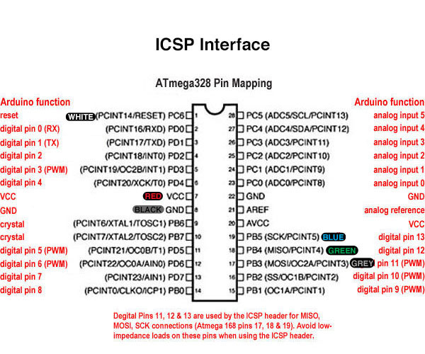
ATmega328 ICSP Connections


Using a 3mm LED with built-in resistor saves space:

ICSP Cable
ICSP Cable


Once again, make a handy reference card, and keep it, err, handy:

ATmega328 ICSP Header Pins
** ICSP GOTCHA **

Here’s a tip that may save you a few headaches. If after programming a completely blank ATmega for the first time the sketch seems to run really slowly, then try burning the bootloader first, then reload your sketch afterwards. The bootloader will be erased, but when burning it the Arduino IDE also sets certain settings in the ATmega correctly for Arduino compatible operation (specifically, it sets the device to use the external 16MHz crystal oscillator rather than the 1MHZ internal one).