Infrared remote control is considered a bit quaint these days – radio frequency modules are now readily available that offer long range, easy interfacing, and low cost. Why create an IR system, then? Apart from having a very particular application in mind (more on this in the coming months), it was a good intellectual exercise that gave me some experience with the interrupt and timer features of the PICMicro microcontrollers.
Principle
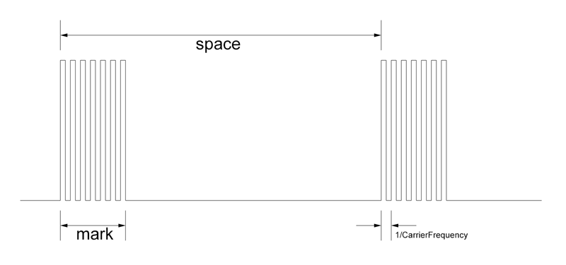
At its most basic level, infrared (IR) remote control works by a transmitter emitting pulse infrared light that is then detected by a receiver. The frequency the IR is pulsed at is called the carrier frequency, and is usually between 30KHz and 56KHz (38KHz is very common). Most systems work by sending data that is encoded into the spaces between short bursts of the pulsed IR light. These short bursts are known as marks.
Protocol
The protocol I’ve devised is much like many of protocols used in remote controls.
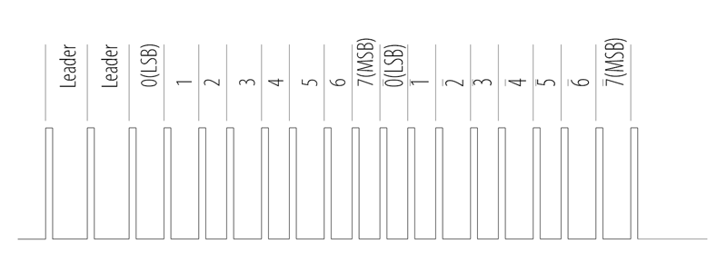
First, 2 ‘leader’ spaces of 932µs are sent to denote the start of a valid signal. The bits are then sent (starting with the least significant bit (LSB)) as 8 spaces; a 0 represented by as 580µs space, and a 1 represented by a 756µs space. A compliment of the byte is then sent for error detection.
Hardware
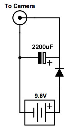
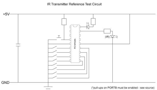
Transmitting IR is simply a case of modulating the output of an IR LED. For short ranges the LED can be driven directly from a microcontroller, for longer ranges the LED can be driven with higher current via a transistor.
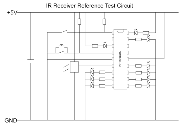
To receive the IR signal the receiver has to be able to detect the pulsing of the light at its carrier frequency. Fortunately, there are easy to use modules to achieve this. I’ve been using the Vishay TSOP1840 module; a 3 pin device that pulls an output pin low whenever IR at the carrier frequency is detected (the TSOP1840 is quite old, and has undoubtedly been superseded by newer devices). The TSOP1840 is optimised to detect a 40KHz carrier, but it will detect a 38KHz carrier albeit with reduced sensitivity.
Reference Implementation
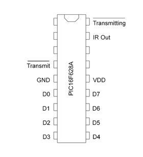
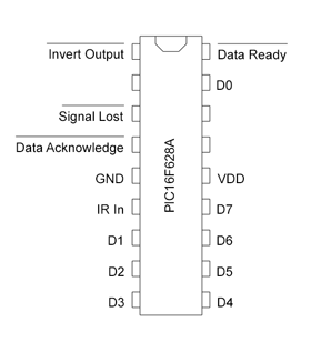
The reference implementation for both receiving and transmitting uses a PIC16F628A microcontroller coded in assembler. Pinouts, circuits and links to code below:
Source code on Github (GNU GPLv3 Licence).
This implementation is a Reference Implementation, which means exactly that – it’s not supposed to be deployed as-is, but to be the basis of a more featured system. I have, for example, modified the transmitter implementation to read the keyboard matrix of an old Atari Jaguar controller which I can now use a generic controller for future projects.